Image:RC membrane circuit.jpg
From Wikipedia, the free encyclopedia
Size of this preview: 800 × 340 pixel
Image in higher resolution (1423 × 604 pixel, file size: 100 KB, MIME type: image/jpeg)

A drawing I made of a basic RC circuit superimposed on a membrane bilayer. Made in CorelDraw!
Caption (from action potential):
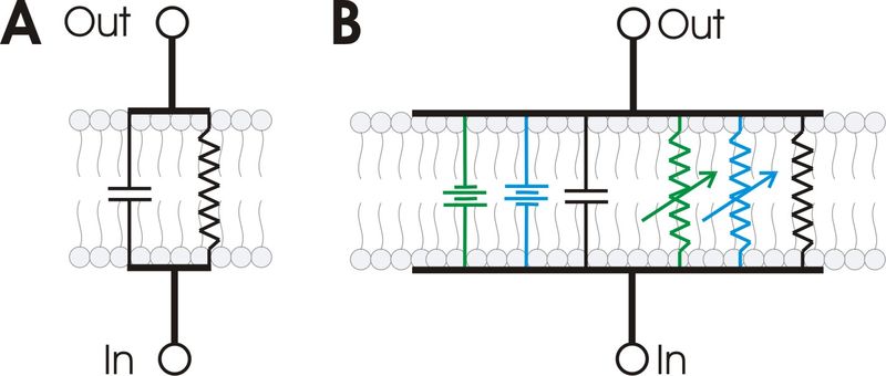
Part A: A basic RC circuit, superimposed on an image of a membrane bilayer to show the relationship between the two. Part B: A more elaborate RC circuit, superimposed on an image of a membrane bilayer. This RC circuit represents the electrical characteristics of a minimal patch of membrane containing at least one Na and two K channels. Elements shown are the transmembrane voltages produced by concentration gradients in potassium (green) and sodium (blue), The voltage-dependent ion channels that cross the membrane ( variable resistors;K=green, Na=blue), the non-voltage-dependent K channel (black), and the membrane capacitance.

Permission is granted to copy, distribute and/or modify this document under the terms of the GNU Free Documentation License, Version 1.2 and no other versions published by the Free Software Foundation; with no Invariant Sections, no Front-Cover Texts, and no Back-Cover Texts.
Subject to disclaimers.
File history
Legend: (cur) = this is the current file, (del) = delete this old version, (rev) = revert to this old version.
Click on date to download the file or see the image uploaded on that date.
- (del) (cur) 16:34, 6 July 2005 . . Synaptidude ( Talk | contribs) . . 1423×604 (102,686 bytes) (A schematic diagram showing the (A) basic electrical characteristics of a biological membrane as an RC circuit, and (B) a more elaborated view showing the electrical elements necessary to carry currents underlying an action potential. Drawn by ~~~~ in Co)
- (del) (rev) 01:15, 6 July 2005 . . Synaptidude ( Talk | contribs) . . 480×595 (33,879 bytes) (A drawing I made of a basic RC circuit superimposed on a membrane bilayer. Made in CorelDraw! {{GFDL 1.2}})
-
Edit this file using an external application
See the setup instructions for more information.
File links
Categories: Images with inappropriate JPEG compression | GFDL 1.2 images