Mars Reconnaissance Orbiter
2007 Schools Wikipedia Selection. Related subjects: Space transport
| Mars Reconnaissance Orbiter | |
|---|---|
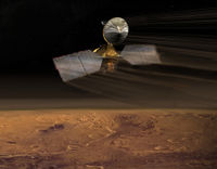
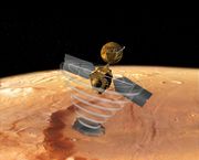
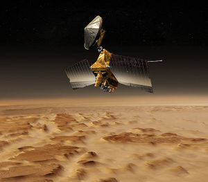 Conceptual drawing of Mars Reconnaissance Orbiter over Mars |
|
| Organization: | NASA |
| Major Contractors: | Lockheed Martin Space Systems, University of Arizona, Johns Hopkins University Applied Physics Laboratory, Italian Space Agency, Malin Space Science Systems, JPL |
| Mission type: | Orbiter |
| Satellite of: | Mars |
| Orbital Insertion date: | March 10, 2006 |
| Launch Date: | August 12, 2005 |
| Launch Vehicle: | Atlas V-401 rocket |
| Mission Duration: | 4 years |
| NSSDC ID: | 2005-029A |
| Webpage: | Mars Reconnaissance Orbiter |
| Mass: | 2,180 kg (4,806 lb) with fuel |
| Power: | Two solar panels, 2,000 watts |
NASA's Mars Reconnaissance Orbiter (MRO) is a multipurpose spacecraft designed to conduct reconnaissance and exploration of Mars from orbit. The $720 million USD spacecraft was built by Lockheed Martin under the supervision of the Jet Propulsion Laboratory. It was launched August 12, 2005 and attained Martian orbit on March 10, 2006. It has recently finished aerobraking, and entered its final science orbit. It is expected to begin its primary science phase in November 2006.
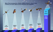
MRO contains a host of scientific instruments such as cameras, spectrometers, and RADAR, which will be used to analyze the landforms, stratigraphy, minerals, and ice of Mars. It will pave the way for future spacecraft by monitoring daily weather and surface conditions, studying potential landing sites, and testing a new telecommunications system. MRO's telecommunications system will transfer more data back to Earth than all previous interplanetary missions combined, and MRO will serve as a highly capable relay satellite for future missions.
MRO joins four other spacecraft currently studying Mars: Mars Express, Mars Odyssey, and two Mars Exploration Rovers. This is the largest number of active spacecraft to study another planet at the same time in the history of space exploration.
Prior to launch
Mars Surveyor Orbiter, an orbiting satellite whose hallmark was a high-resolution camera, was first proposed to NASA in 1999. It was one of two missions being considered for the 2003 launch opportunity; however, during the proposal process the orbiter competed and lost against what became known as the Mars Exploration Rovers. The orbiter mission was rescheduled for launch in 2005, and NASA announced its final name, Mars Reconnaissance Orbiter, on October 26, 2000..
MRO was modeled after NASA's highly successful Mars Global Surveyor to conduct surveillance of Mars from orbit. Early specifications of the satellite included a large camera to take high resolution pictures of Mars. In this regard, Jim Garvin, the Mars exploration program scientist for NASA, proclaimed that MRO would be a "microscope in orbit". The satellite was also to include a visible-near-infrared spectrograph.
On October 3, 2001, NASA chose Lockheed Martin as the primary contractor for the spacecraft's fabrication. By the end of 2001 all of the mission's instruments were selected. There were no major setbacks during MRO's construction, and the spacecraft was moved to John F. Kennedy Space Centre on May 1, 2005 to prepare it for launch.
Launch and orbital insertion
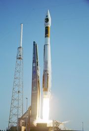
On August 12, 2005, MRO was launched aboard an Atlas V-401 rocket from Space Launch Complex 41 at Cape Canaveral Air Force Station. The Centaur upper stage of the rocket completed its burns over a fifty-six minute period and placed MRO in interplanetary transfer orbit towards Mars.
MRO cruised through interplanetary space for 7.5 months before reaching Mars, and most of the scientific instruments and experiments were tested and calibrated en route. To ensure proper orbital insertion upon reaching Mars, four trajectory correction maneuvers were planned and a fifth emergency maneuver was discussed. However, only three trajectory correction maneuvers were necessary, saving fuel for MRO's extended mission.
MRO began orbital insertion by approaching Mars on March 10, 2006 and passing above its southern hemisphere at an altitude of 370–400 km (190 mi). All six of MRO's main engines burned for 27 minutes to slow the probe from ~2,900 m/s to ~1,900 m/s (6,500 mph to 4,250 mph). The helium pressurization tank was colder than expected, which reduced the pressure in the fuel tank by about 21 kPa (3 psi). The reduced pressure caused the engine thrust to be diminished by 2%, but MRO automatically compensated by extending the burn time by 33 seconds.
Orbital insertion placed the orbiter in a highly elliptical polar orbit with a period of approximately 35.5 hours. Shortly after insertion, the periapsis — the point in the orbit closest to Mars — was 3,806 km from the planet's centre (426 km from its surface). The apoapsis — the point in the orbit farthest from Mars — was 47,972 km from the planet's centre (44,500 km from its surface).
On March 30, 2006, MRO began the process of aerobraking, a three-step procedure that cuts in half the fuel needed to achieve a lower, more circular orbit with a shorter period. First, during its first five orbits of the planet (one Earth week), MRO used its thrusters to drop the periapsis of its orbit into aerobraking altitude. This altitude depends on the thickness of the atmosphere because Martian atmospheric density changes with its seasons. Second, while using its thrusters to make minor corrections to its periapsis altitude, MRO maintained aerobraking altitude for 445 planetary orbits (about 5 Earth months) to reduce the apoapsis of the orbit to 450 km (280 mi). This was done in such a way so as to not heat the spacecraft too much, but also dip enough into the atmosphere to slow the spacecraft down. After the process was complete, MRO used its thrusters to move its periapsis out of the edge of the Martian atmosphere, August 30, 2006.
In September of 2006 MRO fired its thrusters twice more to fine-tune its final, nearly circular orbit approximately 250 to 316 km (155 to 196 mi) above the Martian surface. The SHARAD dipole antenna were deployed the September 16. All of the scientific instruments will be tested and most were turned off prior to the solar conjunction which occurred from October 7, 2006 to November 6, 2006. The "primary science phase" began after the conjunction ended.
On November 17, 2006 NASA announced the successful test of the MRO as an orbital communications relay. Using the NASA rover " Spirit" as the point of origin for the transmission, the MRO acted as a relay for transmitting data back to Earth.
Mission objectives
Beginning in November 2006, MRO will conduct science operations for two Earth years. One of the mission's main goals is to map the Martian landscape with high-resolution cameras in order to choose other landing sites for future missions. These include the Phoenix Lander, which will explore the Martian Arctic, and the Mars Science Laboratory, a highly maneuverable rover. MRO will help planners evaluate both the scientific value and the landing risks for possible landing sites for these missions. It will also provide a transmission relay and critical navigation data during their landing.
MRO will also use its on-board scientific equipment to study the Martian climate, weather, atmosphere, and geology, and to search for signs of water in the polar caps and underground. In addition, MRO will look for the remains of the previously lost Mars Polar Lander and Beagle 2 spacecraft, and will serve as the first step in setting up an internet protocol for the different planets in our solar system. After its main science operations are completed, the probe's extended mission will continue using the communication and navigation system for future lander and rover probes.
Events and discoveries
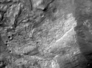
On September 29, 2006, MRO took its first high resolution image from it science orbit. This image is said to resolve items as small as armchairs on the surface (90 cm (3 feet) in diameter).
On October 6, 2006, NASA released detailed pictures from the MRO of Mars' Victoria Crater along with the Opportunity rover on the rim above it.
Instruments
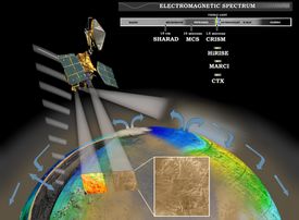
Six science instruments are included on the mission along with two "science-facility instruments", which use data from engineering subsystems to collect science data. Three technology experiments will test and demonstrate new equipment for future missions.
HiRISE
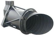
The High Resolution Imaging Science Experiment camera is a 0.5 m reflecting telescope, the largest ever carried on a deep space mission, and has a resolution of 1 microradian (μrad), or 0.3 m from an altitude of 300 km. In comparison, satellite images of Earth are generally available with a resolution of 0.1 m, and satellite images on Google Maps are available to 1 m. HiRISE collects images in three colour bands, 400 to 600 nm ( blue- green or B-G), 550 to 850 nm ( red) and 800 to 1,000 nm ( near infrared or NIR).
Red colour images are 20,264 pixels across (6 km wide), and B-G and NIR are 4,048 pixels across (1.2 km wide). HiRISE's on-board computer reads these lines in time with the orbiter's ground speed, and images are potentially unlimited in length. Practically however, their length is limited by the computer's 28 Gigabit (Gb) memory capacity, and the nominal maximum size is 20,000 × 40,000 pixels (800 megapixels) and 4,000 × 40,000 pixels (160 megapixels) for B-G and NIR images. Each 16.4 Gb image will be compressed to 5 Gb before transmission and released to the general public on the HiRISE website in JPEG 2000 format. To facilitate the mapping of potential landing sites, HiRISE can produce stereo pairs of images from which topography can be calculated to an accuracy of 0.25 m. HiRISE was built by Ball Aerospace & Technologies Corp.
CTX
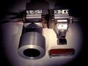
The Context Imager (CTX) provides grayscale images (500 to 800 nm) up to 40 km wide with a pixel resolution of 6 m. The CTX is designed to provide context maps for the targeted observations of HiRISE and CRISM. The optics of CTX consist of a 350 mm focal length Maksutov Cassegrain telescope with a 5,064 pixel wide line array CCD similar to the HiRISE instrument. The instrument will take pictures 30 km (19 mi) wide and has enough internal memory to store an image 160 km long before loading it into the main computer.
MARCI
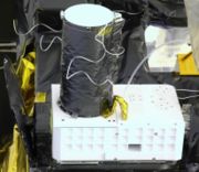
The Mars Colour Imager (MARCI) is a wide-angle, low-resolution camera that views the surface of Mars in five visible and two ultraviolet bands. Each day, MARCI will collect about 84 images and produce a global map with pixel resolutions of 1 to 10 km. This map will provide a daily weather report for Mars, help to characterize its seasonal and annual variations, and map the presence of water vapor and ozone in its atmosphere.
CRISM
The Compact Reconnaissance Imaging Spectrometer for Mars (CRISM) instrument is a visible and near infrared (VNIR) spectrometer that will produce detailed maps of the surface mineralogy of Mars. It operates from 370 to 3920 nm, measures the spectrum in 544 channels (each 6.55 nm wide), and has a resolution of 18 m at an altitude of 300 km. CRISM will be used to identify minerals and chemicals indicative of the past or present existence of water on the surface of Mars. These materials include iron, oxides, phyllosilicates, and carbonates, which have characteristic patterns in their visible-infrared energy.
MCS
The Mars Climate Sounder (MCS) is a spectrometer with one visible/near infrared channel (0.3 to 3.0 μm) and eight far infrared (12 to 50 μm) channels. These channels were selected to measure temperature, pressure, water vapor and dust levels. MCS will observe the atmosphere on the horizon of Mars (as viewed from MRO) by breaking it up into vertical slices and taking measurements within each slice in 5 km (3 mi) increments. These measurements will be assembled into daily global weather maps to show the basic variables of Martian weather: temperature, pressure, humidity and dust density.
SHARAD
MRO's Shallow Subsurface Radar (SHARAD) experiment is designed to probe the internal structure of the Martian polar ice caps. It will also gather planet-wide information about underground layers of ice, rock and possibly liquid water that might be accessible from the surface. SHARAD uses HF radio waves between 15 and 25 MHz, a range that allows it to resolve layers as thin as 7 m to a maximum depth of 1 km. It will have a horizontal resolution as high as 0.3 by 3 km. SHARAD is designed to operate in conjunction with Mars Express's MARSIS, which has lower resolution but penetrates to a much greater depth. Both SHARAD and MARSIS were made by the Italian Space Agency.
Engineering instruments
In addition to its imaging equipment, MRO will carry a variety of engineering instruments. The Gravity Field Investigation Package will measure variations in the Martian gravitational field through variations in the spacecraft's velocity. Velocity changes are detected by measuring doppler shifts in MRO's radio signals received on Earth. The package also includes sensitive on-board accelerometers used to deduce the in situ atmospheric density of Mars during aerobraking.
The Electra is a UHF software defined radio designed to communicate with other spacecraft as they approach, land, and operate on Mars. In addition to protocol controlled inter-spacecraft data links of 1 kbit/s to 2 Mbit/s, Electra also provides Doppler data collection, open loop recording and a highly accurate timing service based on a 5e-13 USO. Doppler information for approaching vehicles can be used for final descent targeting or descent and landing trajectory recreation. Doppler informaion on landed vehicles will also enable scientists to accurately determine the surface location of Mars landers and rovers. The two MER spacecraft currently on Mars utilize an earlier generation UHF relay radio providing similar functions through the Mars Odyssey orbiter. The Electra radio may use the MER spacecraft to prove its functionality but it is not scheduled to provide formal relay services until the 2008 arrival of the Phoenix Mars lander. Because the Electra radio is software defined down to the modem level, new modulation, coding or protocol functions can be added or updated while the MRO spacecraft is in orbit around Mars.
The Optical Navigation Camera images the Martian moons, Phobos and Deimos, against background stars to precisely determine MRO's orbit. Although moon imaging is not mission critical, it was included as a technology test for future orbiting and landing of spacecraft. The Optical Navigation Camera was tested successfully in February and March of 2006.
Engineering data
Structure
Workers at Lockheed Martin Space Systems in Denver assembled the spacecraft structure and attached the instruments. Instruments were constructed at the Jet Propulsion Laboratory, the University of Arizona Lunar and Planetary Laboratory in Tucson, Arizona, Johns Hopkins University Applied Physics Laboratory in Laurel, Maryland, the Italian Space Agency in Rome, Italy, and Malin Space Science Systems in San Diego, California. The total cost of the spacecraft was $720 million USD.
The structure is made of mostly carbon composites and aluminium-honeycombed plates. The titanium fuel tank takes up most of the volume and mass of the spacecraft and provides most of its structural integrity. The spacecraft's total mass is less than 2,180 kg (4,806 lb) with an unfueled dry mass less than 1,031 kg (2,273 lb).
Power systems
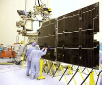
MRO gets all of its electrical power from two solar panels, each of which can move independently around two axes (up-down, or left-right rotation). Each solar panel measures 5.35 × 2.53 m and has 9.5 m² (102 ft²) covered with 3,744 individual photovoltaic cells. Its high-efficiency triple junction solar cells are able to convert more than 26% of the sun's energy directly into electricity and are connected together to produce a total output of 32 volts. At Mars, the two panels produce 2,000 watts of power; in contrast, the panels would generate 6,000 watts in a comparable Earth orbit by being closer to the Sun.
MRO has two nickel metal hydride rechargeable batteries used to power the spacecraft when it is not facing the sun. Each battery has an energy storage capacity of 50 ampere-hours (180 kC). The full range of the batteries cannot be used due to voltage constraints on the spacecraft, but it will allow the operators to extend the battery life—a valuable capability, given that battery drain is one of the most common causes of long-term satellite failure. Planners anticipate that only 40% of the batteries' capacities will be required during the lifetime of the spacecraft.
Electronic systems
MRO‘s main computer is a 133 MHz, 10.4 million transistor, 32-bit, RAD750 processor. This processor is a radiation-hardened version of a PowerPC 750 or G3 processor with a specially-built motherboard. The RAD750 is a successor to the RAD6000. This processor may seem underpowered in comparison to a modern PC or Mac processor, but it is extremely reliable, resilient, and can function in solar flare-ravaged deep space. The operating system software is VxWorks and has extensive fault protection protocols and monitoring.
Data is stored in a 160 Gb (20 GB) flash memory module consisting of over 700 memory chips, each with a 256 Mbit capacity. This memory capacity is not actually that large considering the amount of data to be acquired; for example, a single image from the HiRISE camera can be as large as 28 Gb.
Attitude determination
In order to determine the spacecraft's orbit and facilitate maneuvers, sixteen sun sensors — eight primaries and eight backups — are placed around the spacecraft to calibrate solar direction relative to the orbiter's frame. Two star trackers, digital cameras used to map the position of catalogued stars, provide NASA with full, three-axis knowledge of the spacecraft orientation and attitude. A primary and backup Miniature Inertial Measurement Unit (MIMU), provided by Honeywell, will measure changes to the spacecraft attitude as well as any non-gravitionally induced changes to its linear velocity. Each MIMU is a combination of three accelerometers and three ring-laser gyroscopes. These systems are all critically important to MRO, as it must be able to point its camera to a very high precision in order to take the high-quality pictures that the mission requires. It has also been specifically designed to minimize any vibrations on the spacecraft, so as to allow its instruments to take images without any distortions caused by vibrations.
Telecommunications system
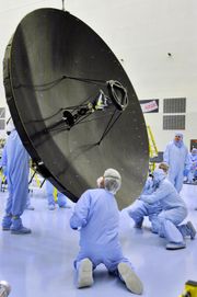
The Telecom Subsystem on MRO is the best telecom system sent into deep space so far. It consists of a very large (3 meter) antenna, which will be used to transmit data through the Deep Space Network via X-band frequencies at 8 GHz, and it will demonstrate the use of the Ka-band at 32 GHz for higher data rates. Maximum transmission speed from Mars is projected to be as high as 6 Mbit/s, a rate ten times higher than previous Mars orbiters. The spacecraft carries two 100-watt X-band amplifiers (one of which is a backup), one 35-watt Ka-band amplifier, and two transponders.
Two smaller low-gain antennas are also present for lower-rate communication during emergencies and special events, such as launch and Mars Orbit Insertion. These antennas do not have focusing dishes and can transmit and receive from any direction. They are an important backup system to ensure that MRO can always be reached, even if its main antenna is pointed away from the Earth.
The Ka-band subsystem is used for demonstration purposes. Due to lack of spectrum at 8.41 GHz X-band, future high-rate deep space missions will use 32 GHz Ka-band. NASA Deep Space Network (DSN) has implemented Ka-band receiving capabilities at all three of its complexes (Goldstone, Canberra and Madrid) over its 34-m beam-waveguide (BWG) antenna subnet. MRO Ka-band demonstration will demonstrate viability of Ka-band for deep space operations. During the cruise phase, spacecraft Ka-band telemetry was tracked 36 times by these antennas proving DSN Ka-band reception functionality at all the antennas. During the primary science phase, Ka-band demonstration will be assigned two passes a week for Ka-band demonstration purposes. The success of Ka-band during cruise also makes it a viable backup for the X-band subsystem on MRO.
Propulsion and attitude control
The spacecraft uses a 1175 L (310 US gal) fuel tank filled with 1187 kg (2617 lb) of hydrazine monopropellant. Fuel pressure is regulated by adding pressurized helium gas from an external tank. Seventy percent of the fuel will be used for orbital insertion.
MRO has twenty rocket engine thrusters on board. Six large thrusters each produce 170 N (38 lbf) of thrust for a total of 1,020 N (230 lbf) meant mainly for orbital insertion. These thrusters were originally designed for the Mars Surveyor 2001 Lander. Six medium thrusters each produce 22 N (5 lbf) of thrust for trajectory correction maneuvers and attitude control during orbit insertion. Finally, eight small thrusters each produce 0.9 N (0.2 lbf) of thrust for attitude control during normal operations.
Four reaction wheels are also used for precise attitude control during activities requiring a highly stable platform, such as high-resolution imaging, in which even small motions can cause blurring of the image. Each wheel is used for one axis of motion. The fourth (skewed) wheel is a backup in case one of the other three wheels fails. Each wheel weighs 10 kg (22 lb) and can be spun as fast as 100 Hz or 6,000 rpm.
