Falkirk Wheel
2007 Schools Wikipedia Selection. Related subjects: Engineering
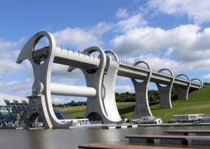
The Falkirk Wheel, named after the nearby town of Falkirk in central Scotland, is a rotating boat lift connecting the Forth and Clyde Canal with the Union Canal, which at this point differ by 24 metres, roughly equivalent to the height of an eight story building.
On 24 May 2002, Queen Elizabeth II opened the Falkirk Wheel as part of her Golden Jubilee celebrations. The opening had been delayed by a month due to flooding caused by vandals who forced open the Wheel's gates.
Design of the Falkirk Wheel
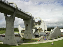
The wheel, which has an overall diameter of 35 metres, consists of two opposing arms which extend 15 metres beyond the central axle, and which take the shape of a Celtic-inspired, double-headed axe. Two sets of these axe-shaped arms are attached about 25 metres apart to a 3.5 metre diameter axle. Two diametrically opposed water-filled caissons, each with a capacity of 80,000 gallons (302 tons), are fitted between the ends of the arms.
These caissons always weigh the same whether or not they are carrying their combined capacity of 600 tonnes of floating canal barges as, according to Archimedes' principle, floating objects displace their own weight in water, so when the boat enters, the amount of water that leaves the caisson is exactly the same as the weight of the boat. This keeps the wheel balanced and so, despite its enormous mass, it rotates through 180° in less than four minutes while using very little power. It takes just 22.5 kilowatts (kW) to power the electric motors, which consume just 1.5 kilowatt-hours (kWh) of energy in four minutes, roughly the same as boiling eight kettles of water.
The wheel is the only rotating boat lift of its kind in the world, and is regarded as an engineering landmark for Scotland. The United Kingdom has one other boat lift: the Anderton Boat Lift in Cheshire. The Falkirk Wheel is an improvement on the Anderton Boat Lift and makes use of the same original principle: two balanced tanks, one going up and the other going down.
How the wheel rotates
The wheel rotates together with the axle which is supported by the 4 metre diameter slewing bearings which are fitted to the ends of the axle and have their outer rings mounted on the plinths which in turn are constructed on top of piled foundations.
The slewing bearing at the machine-room end of the axle has an inner ring gear which in this configuration acts as a rotating annulus. The rotating annulus is driven by ten hydraulic motors which are assembled on a stationary bearing and motor assembly known as the planet carrier which in turn is also mounted onto a plinth similar to the one at the other end of the axle. The driveshafts of the motors have pinion gears which act as stationary planetary gears in this train of gears and engage the rotating annulus ring gear. Electric motors drive a hydraulic pump which is connected to the hydraulic motor by means of hoses and drive the wheel at 1/8 revolution per minute
Construction of the wheel
The wheel was constructed by Butterley Engineering at Ripley in Derbyshire under Millennium Plans to reconnect the Forth and Clyde Canal with the Union Canal, mainly for recreational use. The two canals were previously connected by a series of 11 locks, but by the 1930s these had fallen into disuse, were filled in and the land built upon.
The Millennium Commission decided to regenerate the canals of central Scotland to connect Glasgow with Edinburgh once more. Designs were submitted for a lock to link the canals, with the Falkirk Wheel design winning. As with many Millennium Commission projects the site includes a visitors' centre containing a shop, café and exhibition centre.
How the caissons are kept level
The caissons need to rotate at the same speed as the wheel but in the opposite direction to keep them level and to ensure that the load of boats and water does not drop out when the wheel turns.
The end of each of the caissons is supported on small wheels which run on the inside face of the eight metre diameter holes at the end of the arms, enabling the caissons to rotate freely.
The rotation is achieved by means of a train of gears comprising three eight metre diameter ring gears with external teeth and another two small jockey gears. One of the large gears acts as a stationary sun gear and is fitted loosely over the axle at the machine-room end of the axle and fixed to a plinth to prevent it from rotating. The two small jockey gears, the outer rings of bearings, are fixed to each of the arms of the wheel at the machine-room end of the wheel and act as planet gears. When the motors rotate the wheel the arms swing and planet gears engage the sun gear which results in the planet gears rotating at a higher speed than the wheel but in the same direction as the wheel. The planet gears engage the large ring gears at the end of the caissons causing them to rotate at the same speed as the wheel but in an opposite direction. This keeps the caisons stable and perfectly level.
The dry well
The dry well is a drydock-like port that is isolated from the lower canal basin and kept dry by means of water pumps. If it were not for inclusion of the docking-pit the caissons and extremities of the arms of the wheel would be immersed in the lower canal basin each time the wheel rotates. This would result in a number of undesirable situations developing, such as providing buoyancy to the bottom caisson and the viscosity of the water causing an increase in the required power.
How the canal was routed through the wheel
The route chosen to take the Union Canal to the site of the wheel involved building a completely new section of canal, leading from the original terminus at Port Maxwell to link up with a new basin to the south of the wheel. The water level in this basin is the same as the top section of the wheel, with a 150 metre tunnel joining the two. There are two locks to drop the canal level from that of the Union Canal to this basin. The tunnel was required because the canal had to pass underneath the route of the Antonine Wall without disturbing its archeological remains. Just at this point the canal also passes below a road and the main Edinburgh to Glasgow railway line.
Costs and prices
The Falkirk Wheel cost £17.5 million, and the restoration project as a whole cost £84.5 million (of which £32 million came from National Lottery funds). As of 2006, a ride on the Wheel costs £8 for adults and £4.25 for children aged 3-15 (free for children under 3), OAP concession £6.50, student/UB40 concession £6.50 and family price of £21.50 (2 adults and 2 children) with a discount of 10% for a group of 20 or more.
Future rotating boat-lifts
A similar design of boat-lift has been suggested for a proposed new canal that would run along Marston Vale in Bedfordshire, as part of a large-scale project creating an area of leisure and tourism facilities linked to the future expansion of Bedford and Milton Keynes. The canal would link the Grand Union Canal at Milton Keynes with the River Great Ouse at Bedford.


